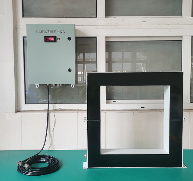
Hall Zero Flux Sensor
Conductive bus bar I through the sensor core, when the measured current through the core to produce a current with the measured current proportional to the magnetic field, installed in the core air gap in the magnetic induction Hall element and the magnetic field proportional to the voltage signal, this signal is processed by the amplifier, the output of a DC current with the measured DC current proportional to the output voltage.
Key Features
Application area
- Technical Specifications
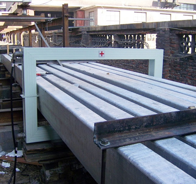
- Application Cases
技术规格
▶ Operating principle of Hall zero flux current sensor:
Hall zero-flux principle of Hall closed-loop current sensors fundamentally solve the inherent shortcomings of Hall components.
Hall zero-flux current sensor (also known as Hall zero-flux current comparator) is the use of iron core to the magnetic field generated by the bus current aggregation, through the Hall components of the detected magnetic field is converted into a voltage signal, through the amplification of the voltage signal and the current converter output current, so that the current through the wire packet on the role of the poly-magnetic core, so that the wire packet in the core of the magnetic field produced by the bus current in the core produced by the magnetic field of equal size and opposite direction, the iron core, the magnetic field produced by the bus current in the core When the size is equal and the direction is opposite, the magnetic flux in the core is zero, and the number of ampere-turns of the wire package is always equal to the number of ampere-turns on the bus.
▶ Typical specifications and performance indicators:
| Model number specification | HLA-I | HLA-II | HLA-III |
| Measuring current | Bidirectional DC/pulsating/AC | Unidirectional DC/Pulsating | Unidirectional DC |
| Structural form | Removable through-hole type | ||
| Accuracy | 0.2、0.1% | ||
| Linearity | 0.02% @ 5%~120%F.S | ||
| Turns error | <±0.04% | ||
| Typical ratio | 5KA/1A | ||
| Response time | ≤1uS | ≤1uS | ≤10mS |
| Temperature effect | <20*10-6/℃ | ||
| Typical power consumption | <10VA/KA | ||
| Supply voltage | AC220V/50HZ、60HZ(±5%) | ||
Operating temperature | -10℃~ +55℃ | ||
| electrical insulation resistance | >20MΩ | ||
| Effect of external magnetic fields | Tolerance <0.1%/IN at 100GS/m | ||
| Output signal | 0-75mV/0-5V/4-20mA or according to the user's requirements | ||
应用案例
Recommendation
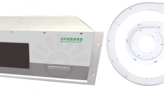 FS201 Fiber Optic Current Measurement Unit
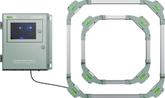 FS205 Large DC Fiber Optic Current Sensor
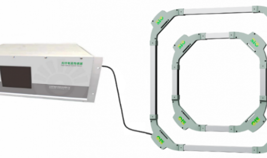 FS206 Fiber Optic Current Sensor
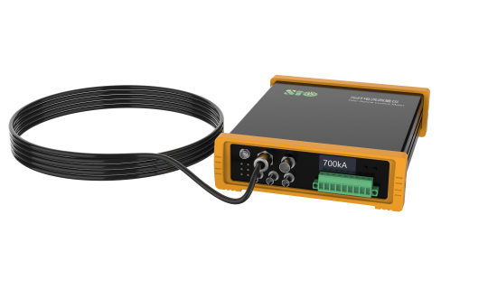 FS207 Fiber Optic Current Meter
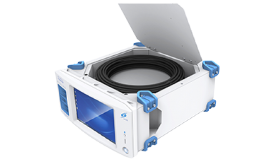 FS208 DC Current Onsite Accuracy-check Instrument
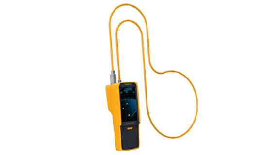 FS209 Hand-held Fiber Optic Current Meter
 FS210 Clamp-on Fiber Optic Current Meter
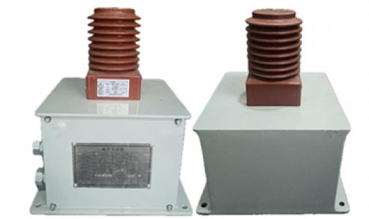 Broadband Voltage Sensors
 Scan to follow WeChat